Guide Bushings for Swiss Lathes: Everything You Need to Know
The Fatal Contradiction in Precision Machining: The Faster the Speed, the Lower the Precision?In Swiss lathe machining, have you ever encountered this dilemma: when increasing the spindle speed, part vibration becomes a frequent issue; when pursuing precision, production efficiency drops drastically; and after changing materials, the positioning system frequently fails? These seemingly unsolvable contradictions all point to the same core component—the design and selection defects of the guide bushing.
As the core positioning element of Swiss lathes, guide bushings ensure both IT5 level precision control and high-speed machining stability through rigid support and dynamic balance technologies. They are the key technological enabler for breaking through the bottleneck in precision machining.
This article will delve into the selection, working principles, and application scenarios of guide bushings, helping you make more precise decisions to ensure process optimization and efficient machine operation.

I.What are the guide bushings of a Swiss lathe?
1. Basic Definition and Core Function
Guide bushings are critical components in Swiss lathes that achieve precision machining by providing high-precision positional support, ensuring the stability of the workpiece during high-speed rotation. Their core functions include:
•Vibration Suppression: Reducing radial runout of the workpiece through a rigid support structure, ensuring surface accuracy during machining.
•Concentricity Positioning: Achieving micron-level positional accuracy in collaboration with the spindle system, meeting IT5 tolerance requirements and above.
•Force System Balance: Counteracting the centrifugal and cutting forces to maintain the workpiece's posture, creating a stable machining environment.
The working principle is based on a "three-point positioning" mechanical model, which forms a three-dimensional stable support system by the cooperation of the front support surface, middle guiding surface, and rear positioning surface, ensuring the relative position accuracy between the tool and workpiece.
2. Structural Design and Key Parameters
Typical guide bushings use a stepped cylindrical structure, and the core parameters are designed according to precision mechanical engineering standards:
•Fit Tolerance: The inner diameter and workpiece use clearance fit (H7/g6), while the outer diameter and machine tool sleeve use interference fit (H7/n6).
•Length-to-Diameter Ratio (L/D): The optimized range is 1.5-2.5, balancing support rigidity and frictional heat generation.
•Surface Treatment: Coatings such as TiCN and DLC are used to enhance wear resistance, making the guide bushings suitable for difficult-to-machine materials like stainless steel and titanium alloys.
II. Rotary vs Fixed: In-depth Analysis of Swiss Lathe Guide Bushing Type
1. Rotary Guide Bushings
Technical Features:
•Drive Method: Linked to the spindle 1:1 via a synchronous belt/gear, eliminating relative sliding between the workpiece and guide bushing.
•Core Components: High-precision angular contact ball bearings (ABEC-7 level) and oil-gas lubrication systems, supporting speeds over 20,000rpm.
•Application Scenarios: Long shaft-type parts (L/D > 5), such as medical implants and precision screw processing.
Advantages: Dynamic balance design effectively suppresses vibration in slender shaft machining, improving concentricity accuracy by over 30%.
2. Fixed Guide Bushings
Technical Features:
•Installation Method: Rigidly fixed to the spindle box, without requiring a drive system.
•Material Selection: Sintered monolithic hard carbide (WC-Co), with radial support rigidity ≥ 50N/mm.
•Application Scenarios: Short shaft-type parts (L/D ≤ 3), such as electronic connectors and clock gears, for high-efficiency machining.
Advantages: Simple and reliable structure, reducing machine tool complexity and manufacturing costs by 40%-60% compared to rotary types.
3. Selection Decision Model
Key Parameters | Rotary Guide Bushing Applicable Scenarios | Fixed Guide Bushing Applicable Scenarios |
Workpiece L/D Ratio | > 5 (Precision machining of slender shafts) | ≤ 3 (Efficient machining of short workpieces) |
Machining Precision Level | IT5-IT6 (High precision required) | IT6-IT7 (Rigidity-prioritized scenarios) |
Spindle Speed Range | 15,000-30,000rpm | < 10,000rpm (Conventional speeds) |
Typical Materials | Titanium alloys, high-temperature alloys | Aluminum alloys, mild carbon steel |
III. Why is it necessary to choose a guide bushing for a Swiss lathe?
1. Precision Assurance System
•Vibration Control: Reduces the first-order vibration amplitude of the workpiece by over 60%, ensuring surface roughness Ra ≤ 0.8μm.
•Thermal Deformation Compensation: Matches the coefficient of linear expansion with the spindle design, controlling axial thermal deformation to ≤10μm/°C.
•Geometric Precision: Significantly improves key indicators such as concentricity (≤0.005mm) and straightness (≤0.003mm/100mm).
2. Production Efficiency Enhancement
•High-Speed Machining: Stable support allows for an increase in cutting speed by 20%-30%, with feed rates reaching over 0.2mm/rev.
•Tool Life: Reduces radial load impacts on tools, extending their life by 15%-25%.
•Automation Adaptability: Ensures ±0.001mm repeatability for reliable robot loading/unloading, reducing downtime.
3. Cost Optimization Logic
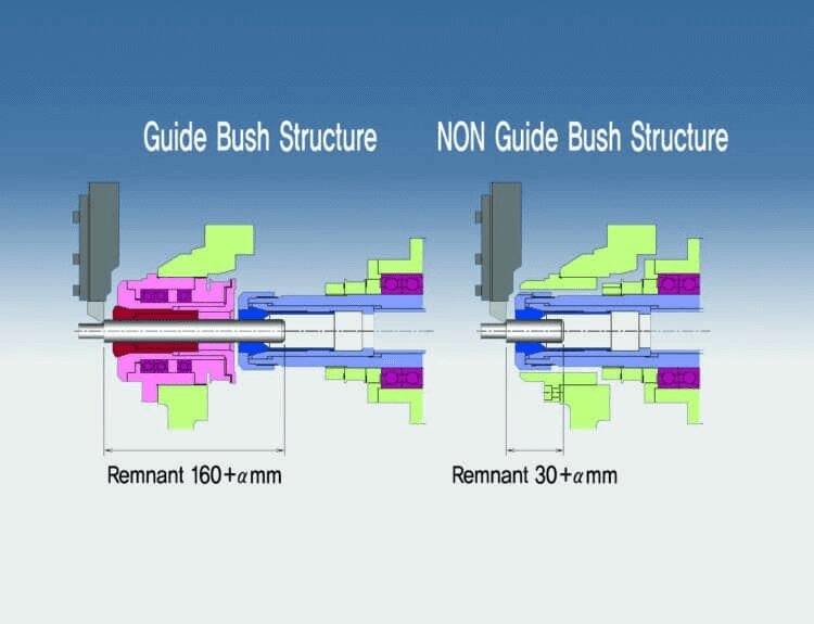
Cost Dimension | Guide Bushing Solution Advantages | Non-Guide Bushing Solution Disadvantages |
Initial Investment | Accounts for 5%-10% of machine tool cost | Lower short-term equipment costs |
Long-Term Maintenance | Calibration cycle extended by 3 times | Frequent precision compensation leads to downtime |
Scrap Rate Control | Reduced to below 1% | Commonly exceeds 5% |
Total Cost of Ownership (TCO) | Reduces by 25%-35% compared to traditional solutions | High hidden costs |
IV. Guide Bushing Working Principles and Technical Features
1. Kinematic Principle Analysis
•Contact Mechanics: Designs contact stress based on Hertzian contact theory, and optimizes the L/D ratio (recommended 1.8-2.2) to control stress within 70% of the material’s allowable value.
•Lubrication Strategy: Grease lubrication for low-speed scenarios (<15,000rpm), oil mist lubrication (5-10μm atomized particles) for high-speed scenarios.
•Thermal Management: Material-matching design (such as carbide and steel spindles) prevents additional compensation for temperature differences (ΔT ≤ 20°C).
2. Material Science Applications
Material Type | Hardness (HRC) | Wear Resistance (Relative Value) | Typical Machining Scenarios |
High-Speed Steel (HSS) | 62-65 | 1.0 | General machining of regular steel parts |
Tungsten Carbide | 89-92 | 3.5 | Machining of stainless steel / titanium alloys |
Zirconia Ceramic | 94-96 | 5.0 | Ultra-precision mirror finishing |
Coating Technologies:
•TiN Coating: General wear-resistant treatment, suitable for sticky materials like aluminum alloys.
•DLC Coating: Ultra-low friction coefficient (0.01-0.03), preventing tool adhesion in copper alloy machining.
•Nanocomposite Coating: Resistant to high temperatures (up to 1100°C), suitable for aerospace high-temperature alloy machining.
V. Installation, Debugging, and Maintenance of a Swiss Lathe
1. Key Installation Process
Concentricity Calibration: Use a laser tool alignment system to align the axis, ensuring the concentricity error between the guide bushing and spindle is ≤0.002mm. Calibration cycles are performed after initial installation and major overhauls.
Fit Tolerance Selection:
•Rotary Guide Bushings: H7/g6 clearance fit (0.005-0.015mm), allowing slight axial movement to compensate for thermal expansion.
•Fixed Guide Bushings: H7/n6 interference fit (0.003-0.008mm), ensuring a rigid connection with the press-fitting machine.
Lubrication System Matching:
•Low-Speed Scenarios (<15,000rpm): Lithium-based grease lubrication, oil hole spacing ≤50mm.
•High-Speed Scenarios: Oil mist lubrication system, pressure 0.3-0.5MPa, oil volume 0.1-0.2ml/min.
2. Daily Maintenance Norms
Wear Detection:
•Visual Inspection: Coating peeling, guide surface scratches (depth > 0.05mm requires replacement).
•Instrumental Detection: Measure inner diameter wear weekly using a micrometer (alert if the increase > 0.01mm).
Cleaning and Maintenance:
•Use compressed air (pressure 0.6MPa) daily to clear chips and clean the guiding surface with alcohol wipes.
•Change the grease every 200 hours, and clean the bearing chamber for high-speed guide bushings.
3. Common Problem Solutions
Problem | Possible Cause | Solution |
Processing Precision Out of Tolerance | Guide bushing wear / Installation deviation | Replace guide bushing / Recalibrate concentricity |
Abnormal Vibration Noise | Insufficient lubrication / Bearing damage | Add lubrication / Replace bearing components |
Workpiece Surface Pulling | Coating failure / Chip embedding | Replace coated guide bushing / Optimize chip removal groove |
Guide Bushing Temperature Rise Too High | Tight fit / Lubrication failure | Adjust fit tolerance / Check for oil mist nozzle blockage |
VI. CNC Swiss Lathe Selection Guide: From Requirements to Solution
1. Input Machining Parameters
Workpiece Characteristics | Rotary Guide Bushing Recommendation | Fixed Guide Bushing Recommendation |
Material Hardness | HRC30+ (Titanium alloys, stainless steel) | HRC30- (Aluminum alloys, copper alloys) |
Machining Length | >50mm (Slender shafts) | <30mm (Short shafts / Disk-type parts) |
Precision Requirements | IT5 level and above (Medical / Optical) | IT6-IT7 level (General precision parts) |
2. Machine Tool Compatibility Assessment
•Spindle Type: Sliding bearing spindles should prioritize fixed guide bushings (for rigidity matching), while rolling bearing spindles can use rotary guide bushings (for dynamic balance).
•Cooling System: Internal cooling machine tools should have φ0.5mm cooling holes reserved for the guide bushing, while external cooling systems require splash-proof designs.
•Control System: Machine tools with C-axis synchronization can support dynamic control of rotary guide bushings; for regular machines, fixed guide bushings are recommended.
3. Economic Analysis Model
Initial Cost | Rotary Guide Bushing ($2,000-$5,000) | Fixed Guide Bushing ($800-$2,000) |
Service Life | 5,000 hours with normal maintenance | 8,000 hours with normal maintenance |
Return on Investment | For precision-sensitive parts, rotary guide bushing pays off in 6-12 months |
VII. Conclusion
Guide bushings are the core components for precision machining in Swiss lathes, optimizing both positioning design and material technology to balance machining precision (IT5 level and above) with efficiency. The selection, installation, and maintenance of guide bushings directly affect the stability and economic efficiency of precision part processing, serving as a crucial technical link between machine performance and part quality.
As a Chinese machine tool manufacturing solution provider, Minnuo offers Swiss lathes and compatible guide bushing systems, including both rotary and fixed types, to meet the precision and efficiency demands of different machining scenarios. Whether you need equipment tailored for complex machining processes or require solutions for guide bushing selection, maintenance, and other technical issues, feel free to contact us through official channels. Based on reliable equipment and full-process technical services, we provide comprehensive solutions from equipment to processes.

 Email
Email sales1:+1 213 865 6527